Start with configuration
Lead style, insulation, and encapsulation determine how the part fits electrically and mechanically.
Technical Information
With the variety of physical configurations, R25 values, and tolerances available, selecting the right NTC thermistor starts with the application requirements.
Lead style, insulation, and encapsulation determine how the part fits electrically and mechanically.
R25 value, R/T curve, and tolerance define how the thermistor behaves in the measurement range.
North Star Sensors part numbers encode series, coating, resistance, curve, and tolerance choices.
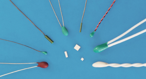
NTC thermistors are small, rugged ceramic semiconductors manufactured from compositions of the oxides of metals. Oxides of manganese, nickel, cobalt, copper, and/or iron are common. Each NTC thermistor composition or mix has a specific ratio of metal oxides which defines the thermistor’s physical dimensions, R/T curve, and its resistance at 25 °C.
NTC thermistors exhibit a relatively large change in resistance vs. temperature, typically on the order of -3% to -6% per °C, providing a much greater sensitivity or signal response to changes in temperature when compared to other temperature sensors, such as thermocouples and RTD’s.
With the variety of physical configurations, R25 values, and temperature/resistance tolerances, NTC thermistors are the most versatile temperature sensor available. North Star Sensors manufactures its NTC thermistors from the highest grade raw materials and controls every step of the manufacturing process.
Leads - Depending on the thermistor configuration, lead styles vary. Typical lead gage varies from 38 AWG to 26 AWG. Leads may be insulated or uninsulated. Common lead materials are copper, copper alloy, and nickel.
Coating/Encapsulation - Epoxy coatings are typical. Some thermistor styles are encapsulated in a polyimide tube or plastic cup.
R25 Values - Typical R25 values range from 50 Ω to 100 kΩ. An R25 of 10 kΩ is one of the most common configurations.
Point-Matched Tolerance - A point-matched tolerance is a ±% resistance tolerance at specific temperature point. The most common reference temperature point is at 25 °C.
Temperature Tolerance - A temperature tolerance is a ± degree C tolerance specified over a temperature range. Typical temperature tolerances range from ±0.5 °C to ±0.1 °C.
Sample leaded part number
1A
Series
E
Coating
103
R25 Digits
R
Resistance
44
R/T Curve
T1A
Tolerance
The example 1AE103R44T1A shows how a leaded thermistor part number maps each code group to a mechanical or electrical selection.
The first two characters identify the base thermistor style, including details such as lead type and overall length.
| Series Code | Description |
|---|---|
| 1A | 30 AWG tin-plated copper, 2" L |
| 1B | 28 AWG tin-plated copper, 2" L |
| 1C | 32 AWG tin-plated copper, 3" L |
| 1D | 32 AWG tin-plated Alloy 180, 3" L |
| 3A | 38 AWG nickel, insulated bifilar, 3" L |
The third character specifies the coating or encapsulation style used on the thermistor.
| Code | Description |
|---|---|
| E | Epoxy |
| T | Polyimide tube with epoxy |
The fourth and fifth characters carry the first significant digits of the resistance at 25 °C, the sixth character gives the number of trailing zeros, and the seventh character R marks the resistance field.
| R25 Code | Resistance at 25 °C |
|---|---|
| 104 | 100,000 Ω |
| 503 | 50,000 Ω |
| 303 | 30,000 Ω |
| 103 | 10,000 Ω |
| 502 | 5,000 Ω |
| 222 | 2,252 Ω |
The eighth and ninth characters identify the R/T curve and the NTC characteristic at 25 °C. For example, curve 44 represents an NTC value of -4.4%/°C at 25 °C.
| Curve | Typical R25 Values |
|---|---|
| 44 | 1,000 Ω - 100,000 Ω |
| 35 | 50 Ω - 500 Ω |
| 38 | 150 Ω - 1,500 Ω |
| 40 | 5,000 Ω - 50,000 Ω |
| 43 | 20,000 Ω - 50,000 Ω |
| 47 | 10,000 Ω - 150,000 Ω |
For temperature tolerances, the tenth character T marks a temperature tolerance and the next two characters define the tolerance and temperature range. For point-matched tolerances, the tenth character P marks a resistance tolerance at 25 °C and the following character defines the allowable percent tolerance.
| Tolerance Code | Description |
|---|---|
| T1A | ±0.1 °C from 0 °C to 70 °C |
| T1B | ±0.1 °C from -20 °C to 50 °C |
| T1C | ±0.1 °C from 0 °C to 100 °C |
| T2A | ±0.2 °C from 0 °C to 70 °C |
| T2B | ±0.2 °C from -20 °C to 50 °C |
| T2C | ±0.2 °C from 0 °C to 100 °C |
| T9A | ±1.0 °C from 0 °C to 70 °C |
| P1 | ±1% resistance tolerance at 25 °C |
| P2 | ±2% resistance tolerance at 25 °C |
| P5 | ±5% resistance tolerance at 25 °C |
Sample leadless part number
A
Configuration
2
Electrode
A
Size
103
R25 Digits
R
Resistance
44
R/T Curve
P2
Tolerance
W
Packaging
The example A2A103R44P2W shows how a leadless thermistor part number maps each code group to contact style, electrode, size, resistance, curve, tolerance, and packaging.
The first character represents the style of the contacts.
| Configuration Code | Description |
|---|---|
| A | Top and bottom contacts |
| B | End banded contacts |
The next character specifies the conductive material used in the electrical contact.
| Electrode Code | Description |
|---|---|
| 1 | Silver |
| 2 | Gold |
The size code represents the length, width, and height of the thermistor chip, including the height of the electrode material. Height is considered the dimension from one electrode to the other if one electrode is facing down and the other is pointed upward.
| Size Code | Length x Width | Height |
|---|---|---|
| A | 0.017" × 0.017" (L x W) | 0.005" (H) |
| B | 0.027" × 0.027" (L x W) | 0.011" (H) |
The next three characters define the resistance at 25 °C: the first two are the starting digits and the third gives the number of trailing zeros. The final character R marks the resistance field.
| R25 Code | Resistance at 25 °C |
|---|---|
| 104 | 100,000 Ω |
| 503 | 50,000 Ω |
| 303 | 30,000 Ω |
| 103 | 10,000 Ω |
| 502 | 5,000 Ω |
| 222 | 2,252 Ω |
This section identifies the R/T curve and the NTC characteristic at 25 °C. For example, curve 44 represents an NTC value of -4.4%/°C at 25 °C.
| Curve | Typical R25 Values |
|---|---|
| 44 | 1,000 Ω - 100,000 Ω |
| 35 | 50 Ω - 500 Ω |
| 38 | 150 Ω - 1,500 Ω |
| 40 | 5,000 Ω - 50,000 Ω |
| 43 | 20,000 Ω - 50,000 Ω |
| 47 | 10,000 Ω - 150,000 Ω |
For point-matched tolerances, the starting character P represents a point-matched tolerance at 25 °C and the next character represents a ±% resistance tolerance at the given temperature point.
| Tolerance Code | Description |
|---|---|
| P1 | ±1% resistance tolerance at 25 °C |
| P2 | ±2% resistance tolerance at 25 °C |
| P5 | ±5% resistance tolerance at 25 °C |
This final code identifies the product packaging.
| Packaging Code | Description |
|---|---|
| W | Waffle pack |
| B | Free floating in bag |